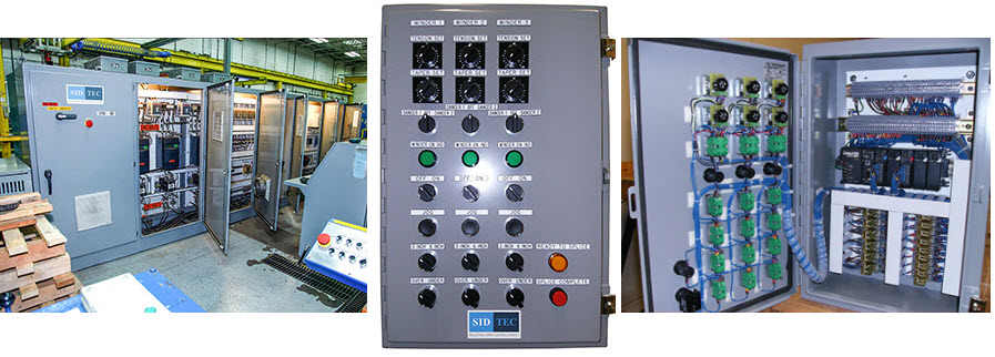
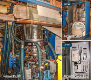
SID-TEC control panels are designed and built for solid functionality, ease of use and fast maintenance…
1) Control Panel Documentation:
The Engineering Documentation must communicate the complete picture of what the control system is doing and how the hardware is setup and connected. The documentation is used first as a blueprint for the panel wiring person to connect all the hardware together, and at a later date for anyone to follow the system connection of the controls in use for trouble shooting of problems should they arise.
a) Drawing Sheets:
SID-TEC uses a standard B size sheet of paper which is 11 by 17 inches.
Each sheet has a title block section along the bottom of which there are 4 sections from left to right.
Section 1: Is for Notes and Comments.
Section 2: Has 8 separate sub sections; Engineered by, Drawn by, Approved by, Accepted by, Redrawn by, Auto Cad Number, Sheet number and the OF and the total number of sheets within a set, Drawing / Part Number,
Section 3: Customer Section; Company Engineered For, Description of Drawing contents.
Section 4: SID-TEC Logo and Address section.
The section above the 4 blocks is the main body of the drawing, which has letters from A to H from top to bottom along the left hand margin and numbers from left to right 1 to 15 across the top.
These letters and number are used in the drawing as a part of a specific item location tool. These letters and numbers work with the sheet number and allow for navigation through the drawings.
b) Parts Designation:
Parts within the schematics are handled in 2 separate ways:
i) Parts which have a standard electrical symbol or are made up of standard symbols.
A complete list of the symbol and its representation can be found on our separate explanation sheet.
ii) Parts that have no standard symbols.
These parts are designated by a solid bold outline rectangular frame with square connection terminal boxes and related numbers as represented by the part, along with a designated short form explanation for each terminal. The part will have a full name and a short form name. The short form name is used for contacts or functions where the part is used in other control circuits. These short form names will also have a note which indicates where these functions have been used and are located, and the contact or other control will also have a cross reference.
Each part will have a short form number, this will be expanded to give more information and then a list will be given of locations where these parts are being used.
As an example: A Run Relay will have the short form designation “RR“ and across from where the relay coil is located will be the description RUN RELAY. A director “ ON SHT “ or “TO SHT“ or “FROM SHT“ is followed by a number dash letter and number. Example: (TO SHT, 4 – D14) means that that relay control is used on sheet number 4 in the cross location D horizontal and 14 vertical location of the sheet.
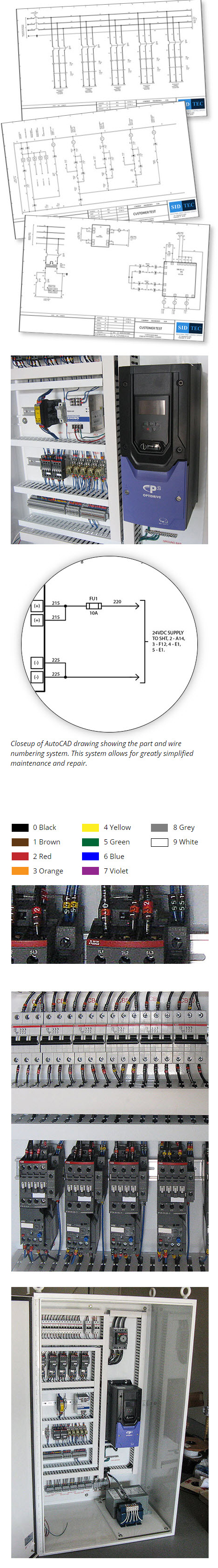
Wire numbers are assigned determined by sheet of origin. The sheet number is the first number, and the last 2 numbers are the wire number for that specific sheet. As an example: wire number “425” indicates that this has its origin on sheet number 4, and the number 25 denotes the wire number on this sheet. An arrow point or tail point will also be followed by a director “ON SHT“ or “TO SHT“ or “FROM SHT“ followed by a number dash letter and number, showing where this wire is being used or where this goes from sheet to sheet on items such as a control power supplies.
Closeup of AutoCAD drawing showing the part and wire numbering system. This system allows for greatly simplified maintenance and repair.
2) Wiring:
a) Numbers:
Wire numbers are used as a standard, letters are only used where an existing system is being added to in order to keep the existing standard where letters and numbers have been used and are in place.
SID-TEC uses the CE compliant wire numbers which are tubular and slip over the wire. They are color coded and have a laser edged number embedded. The color code follows the resistor color code system used and recognized worldwide.
b) Wires:
The wires used in the panels have their own special designation and make working with our equipment very predictable. Regardless of wire size, the voltage and current type being conducted are being conducted are designated by the colors which are listed below.

Safety: The Yellow wires are accompanied by a warning label to indicate that the power may be on when the panel’s main circuit breaker or disconnect switch has been turned off. The warning label will also (if known) indicate the point the power on these yellow wires is being fed from. These wires are most commonly used for panel lighting and power outlet receptacles which are needed when the panel has been turned off.
3) Panel layout:
The panels are laid out so that items that produce a lot of heat are positioned to not affect parts that don’t do well with a lot of heat. Heavy items are also, where possible, mounted lower in the panel so that the panels do not become top heavy and prone to tip over.
Wherever possible, wires are run in nylon wire ducts. The wire duct is secured with nylon rivets so as to ensure there are no current-conductive objects within the duct system.
Parts are mounted onto 35mm DIN rail where possible and the DIN rail is mounted to the back plate using stainless steel pan head screws. The mounting screw holes are always tapped. Where parts are not DIN rail mountable they are mounted individually with stainless steel hardware, the mounting holes are always tapped, Where the parts are large or heavy the bolts are inserted and locked from the rear to form studs which support the parts, and it is then secured to these studs with nuts and washers.
Wire splicing is not permitted within the panel.
Wiring coil and transient suppressor leads may have soldered splices to extend the leads.
Wires are always numbered on both ends.
Terminals always have the same number as the wire connected to them.
Our electrical engineering expertise will solve your long term machinery problems.
Call us at (727) 581-5620.
Project Writeups


Our Clients Include: