Client Writeups
Tampa International Airport
SID-TEC updates propulsion motor controls for Tampa International Airport’s parking lot transport trains…
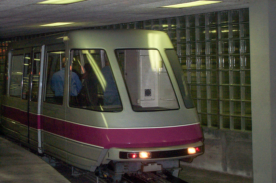
ABOVE: Automated transport shuttle trains at Tampa International Airport used to ferry passengers to and from the car parking structure. Due to improperly balanced controls, the travel drives were not operating together, producing a shuddering and bumpy ride for passengers. SID-TEC’s engineers were able to work out a hardware and software solution to control all the motors so that they were working in harmony and not against each other.
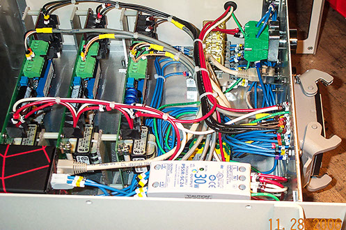
Above is a photo of the power signal isolators, power supply and the UPC (Universal Process Controller) built into a 19inch rack mounting enclosure fitted with connection plugs for ease of use.
PROJECT CHALLENGES
Solving motor drive problems in train systems for Tampa International Airport to make all motors act as a unit, eliminate shuddering and make the ride smoother for passengers
The transport trains from Tampa International Aiport’s car parking areas had been built using ABB Analog DC 4 quadrant drives which were now being problematic, and spare parts were unobtainable for these outdated controls. Bombardier had purchased some updated ABB DCS 400 microprocessor 4 quadrant DC drives from the ABB factory representatives for this product in Florida, but wanted to know who would be able to provide service and support for the product. The factory representative called on SID-TEC’s head of engineering, Mike Holdsworth, and requested support and service during this upgrade.
SID-TEC went out to review the project and immediately predicted a major problem in upgrading the DC drives from the old analog models to the new microprocessor units. This is in the form of the operation of the 4 quadrant DC Drive, which in simple terms means that using solid state devices the drive can propel the motor in the forward direction (Quadrant number 1), apply braking to slow down and stop rotation of the motor in the forward direction (Quadrant number 3), propel the motor in the reverse direction (Quadrant number 2) and apply braking to slow down and stop the motor in the reverse direction (Quadrant number 4). The result is that if the drive determines that the motor is going faster than it should it reverts to putting the braking into effect to slow the motor down to the correct speed. This is the inherent nature of this type of drive and alone they work very well and the more modern the drive the more precise is the motoring and braking of the motor and they have a much tighter accuracy of the exact speed control of the motor.
The train has a set of wheels in the front and a set in the rear and there is about 40 feet between the front and rear wheels, each of the wheel sets has a driving motor and separate motor controlling DC drive. One set of wheels are pulling the train and the other set pushing the train, the wheels are truck tires and they are not identical in diameter, with people sitting at random in the front or back as they choose so speeds and loading can be very different between the front and rear propulsion wheels.
The next problem comes from the train when it goes around a corner or turn where the lead wheels are in the turn while the rear wheels are still on the straight section so loading and speed changes take place on every turn, with all this to have to contend with there was more. The track around the airport is in the shape of a tennis racket so the train goes around once in the forward direction then goes around the next turn in the reverse direction so the front and rear wheels change place every time a lap is completed, so with all of these changing variables trying to speed match 2 accurate microprocessor drives was not going to be something that could be done.
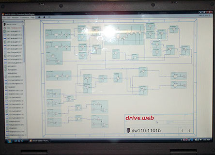
Above is a photo of the traction control software created in this open architecture modular function block format which provided the smooth accurate motor controls.
Mike Holdsworth received his training on the gold mines in South Africa where he studied subjects that are not taught in the standard engineering schools today, applied science and applied physics are two of the subjects he was trained in. Drawing on this knowledge, he was able to predict the total effect of all of the problems and resolve all the problems with a single solution.
The trains were locked into the existing operation which specified that both drives had to be operated in speed regulation mode and as speed matching these drives and motor was never going to be an option in addition setting the drives up so that they were so sloppy in their regulation that they would not fond each other would produce such inaccuracy that it would not be possible to stop at an exact location at the stations and the ATO train controlling system will not tolerate an out of position of more than a few feet and if this is repeated the system will shut down the train, so this was also not a viable option.
Traction Control:
Most engineers know about current control as a first option and then speed control as a second option, but most don’t know that there is a more senior control method for controlling two motors together called “load share”. While the way I do this is my own invention and choice it is also proprietary information. I have heard of a very few others who have also solved this problem in a slightly different manner, which works much like in an automobiles traction control where they force both driving wheels to work together instead of one wheel spinning and the other doing nothing. By forcing each of the two motors to do an equal amount of work they will force themselves to be at the correct and accurate speed at all times.
The end result was that the trains operated effectively and smoothly with great speed regulation and accuracy, the responses were softened to make the ride smoother for the comfort of the passengers. There was no longer any shuddering going around the turns or slowing into the stations or when exiting the station during acceleration.
The traction control systems were then built into some 19 inch racks and were mounted in a slot below the ATO control equipment making this a modular item that could be changed out in the unlikely event of a failure.